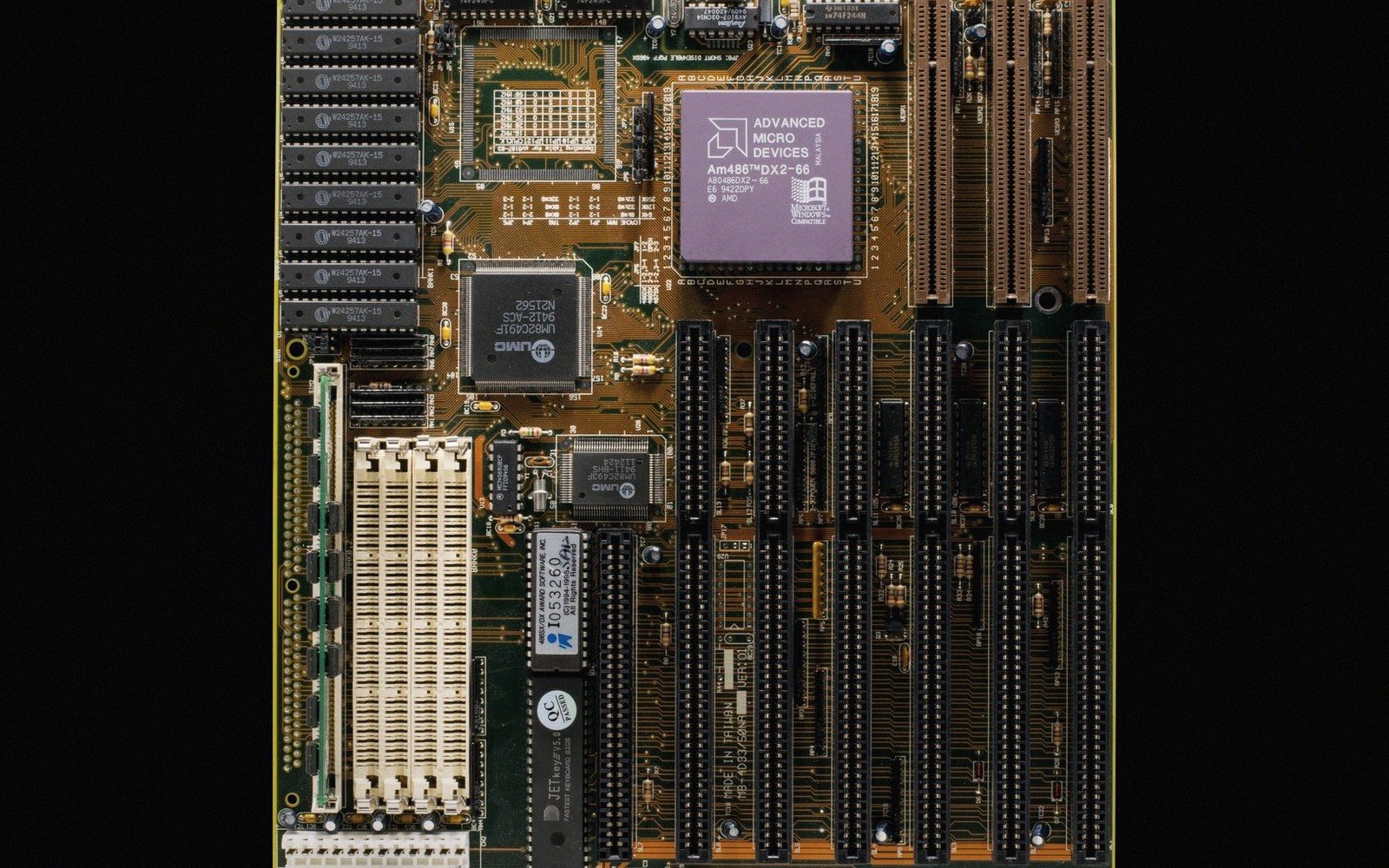
It writes bits into memory and moves on — no debug port, no IDE, no ceremony.[1]
§ 01The Job Is Simpler Than It Looks
A device programmer has one task: it takes a binary file and puts it into a chip's non-volatile memory, reliably and quickly, in a form the chip can execute or use. That is the whole job. The programmer does not run your code, does not help you find a bug, does not hold a connection open while you step through variables. It writes, verifies, and releases the part.
 Enlarge ⤢
Understanding that narrow purpose clears up most of the confusion people have when they first encounter the tool. A programmer is not a debugger. It is closer in spirit to a CD burner than to a breakpoint: you load an image, you press go, you get a programmed device. Cycle times in production can drop to a few seconds per chip; on a factory floor that distinction matters enormously.
The binary it works from is typically a hex or binary file — an Intel HEX, Motorola S-record, or raw .bin — produced at the tail end of the build toolchain. The programmer consumes this file directly, with no compiler or linker involved at the programming stage. What goes in is exactly what the build process produces.
| Interface | Wires | What it does | Reach for it when |
|---|---|---|---|
| ISP | 3–4 + power | Programs the part in circuit through a peripheral it already has. | Production programming on a board with no debug need. |
| JTAG | 4–5 | Programs and debugs, and can chain several devices on one port. | Boards with several programmable parts, or boundary-scan test. |
| SWD | 2 + power | Programs and debugs over two wires — the usual choice on ARM parts. | Almost always, on anything Cortex-M, if you have the pins. |
| Bootloader | 2 (a serial port) or none | The part programs itself from code already resident in it. | Field updates, or where no programmer will ever be attached. |
§ 02Sockets, Clips and In-Circuit Adapters
Hardware programmers come in two main physical arrangements, and choosing between them usually depends on where you are in a product's life.
Gang and socket programmers hold blank devices in zero-insertion-force (ZIF) sockets before the parts ever reach a board. A ZIF socket accepts a chip with no insertion force, locks it with a lever, and releases it cleanly — important when you are cycling through hundreds of parts without damaging leads. Gang programmers extend this to four, eight, or more sockets operated in parallel, all written simultaneously from the same image. This is the production floor model: blank chips in, programmed chips out, hand them to the pick-and-place machine.
Socket adapters translate between the programmer's universal connector and the physical package of the chip you are programming. A SOIC-8 in a DIP socket needs an adapter; so does a QFP, an SSOP, or any other surface-mount package that will not drop into a through-hole ZIF. The adapter is just a mechanical and electrical bridge — it carries the same signals, it just reaches them differently.
In-circuit programming goes the other way: the chip is already on the board, and the programmer reaches it through a header or test pad. ISP — in-system programming — is the classic form of this. An SPI or UART connection, a few signal lines, and the chip reprograms itself using its own logic while sitting in the circuit. The board's power supply is usually active; the programmer talks to the chip's built-in bootloader or programming interface. This is how most hobbyist and small-run work gets done: you solder the board up once and update it repeatedly without ever touching a socket.
JTAG and SWD — the interfaces you see on Arm Cortex-M parts — can also be used to write flash, and often are. But calling that "programming" can obscure a distinction worth keeping. When you write flash over JTAG you are genuinely programming the device. When you use JTAG to halt the core, set a breakpoint, and inspect registers, that is debugging — a fundamentally different activity that uses the same physical connector. The connector looks the same; the purpose is completely different.
§ 03Why the Distinction Between Programming and Debugging Matters
This point deserves its own moment because the hardware often blurs it. Many modern development boards ship with an on-board debug probe — a small secondary microcontroller that speaks USB to your laptop and JTAG or SWD to the target chip. It can program the flash and it can debug. Convenient, absolutely. But that convenience can leave you unclear on which mode you are actually in, and what each mode demands.
Programming needs timing and signal integrity but is forgiving in real time — it writes, verifies, done. Debugging needs a live CPU, a running clock, and a maintained connection; pull the power or let a watchdog fire and you lose the session. The two activities make different demands on the hardware and the workflow. In production you want the former; on a bench chasing a fault you want the latter.
Standalone programmers — the kind that sit on a bench or mount in a fixture — tend to be optimised hard for the programming side. They know device families deeply, they store verified programming algorithms, they handle device-specific timing requirements, they log pass and fail. They are not general-purpose tools; they are appliances for a specific operation.
A good rule of thumb: reach for a dedicated programmer when you need repeatable, logged, production-quality writes. Reach for a debug probe when you need to understand what the code is doing while it runs. The two tools sit side by side on a well-equipped bench — they are not substitutes for each other.
Notes
- Programming and debugging are different jobs. Plenty of tools do both; plenty of cheap ones only claim to. ↩