§ 01Getting the current budget right before writing a line of code
A coin cell holds roughly 200–240 milliamp-hours. A small LiPo might give you 500 mAh. Neither is much when a microcontroller running flat out at a few milliamps will drain them in days. The arithmetic forces a discipline that software-only thinking never demands: you have to know where every microamp goes, and you have to arrange the hardware and firmware so the expensive moments are rare.
This is not about clever tricks. It is about understanding the three places current actually disappears — the MCU itself, the peripherals hanging off it, and the voltage regulation chain — and then applying duty cycling and sleep modes systematically to each.[1]
This is not about clever tricks.
§ 02Where the current goes
The microcontroller core. A Cortex-M0+ running at 48 MHz on a modern 90 nm or smaller process might draw 3–6 mA in active mode. Cut the clock to 4 MHz and that figure drops roughly proportionally, because dynamic power scales with frequency. Cut the voltage — many MCUs now support a range from 1.8 V to 3.6 V — and power drops with the square of the supply. These two knobs, frequency and voltage, are the most powerful tools in your active-mode budget, and most datasheets publish current against both axes. Always read the datasheet curves, not just the headline number.
 Enlarge ⤢
Peripherals inside the MCU bleed current whether or not you use them. A 12-bit SAR ADC left running, a UART with its oscillator enabled, timers ticking away — each module adds its slice. Every modern MCU exposes a peripheral clock gate register. Turn off the clock to any block you are not actively using. This is unglamorous housekeeping but it can save hundreds of microamps on a well-populated part.
External components. The sensor, radio or display attached to your MCU is often the biggest consumer in the whole system, yet it is the piece engineers think about last. A small OLED display can pull 10–20 mA. A Bluetooth LE radio in advertising mode averages a few milliamps. An LTE-M module waking to send a packet may spike to 200 mA or more. These loads dwarf the MCU itself. If you can switch them off between uses — through a load switch or a GPIO-controlled power rail rather than just a software disable — the idle current drops to the leakage floor of the MOSFET, typically in the nanoamp range.
The regulator. A linear LDO with a 10 µA quiescent current sounds harmless. At a 1% duty cycle — the MCU active one percent of the time — it is still burning 10 µA continuously. Over a year that is roughly 87 mAh just keeping the lights on in the regulator. Some LDOs designed for low-power applications have quiescent currents below 1 µA; they cost a little more but earn that cost quickly. If the MCU runs from a battery that is nominally at the right voltage, consider whether a regulator is needed at all, or whether a simple LC filter suffices.[2]
§ 03Sleep modes and what they actually mean
Every serious low-power MCU has several sleep states, usually named something like Sleep, Deep Sleep, and Stop or Hibernate, though the terminology varies by vendor and family. The key variable is which clocks and which RAM banks stay powered.
Sleep typically halts the CPU pipeline but leaves peripheral clocks running. Current drops to maybe 20–40% of active. Wake time is fast — a single clock cycle in many implementations. This mode makes sense when a peripheral (a hardware UART or SPI block) needs to keep running between CPU interventions.
Deep sleep or stop cuts most or all internal clocks, keeps RAM powered, and may leave only a low-power oscillator and a real-time counter running. Current can drop to tens of microamps on older processes, single-digit microamps on modern ones. Wake latency is longer — a millisecond or two is common while clocks restart and stabilise — which matters if your application has tight real-time requirements.
Hibernate or shutdown powers down almost everything, sometimes including RAM. The MCU resumes from a full reset. State must be saved to non-volatile memory before entry. Current at this level can reach the hundreds of nanoamps range, occasionally lower. The trade-off is a long and disruptive wake path.
Arm's Cortex-M architecture provides the WFI (Wait For Interrupt) and WFE (Wait For Event) instructions as the software entry point to whatever sleep mode the silicon vendor has wired up. The depth of sleep reached after a WFI depends entirely on how the vendor has implemented the SCR register's SLEEPDEEP bit, and associated power management logic. Read the vendor's application note, not just the Arm architecture reference.
§ 04Duty cycling: the system view
A duty cycle is a ratio: the fraction of time the system is doing active work versus sleeping. If your sensor node samples once a minute, the measurement plus radio transmission might take 50 milliseconds. That is a duty cycle of about 0.08%. At that ratio, even a 5 mA active current averages out to around 4 µA — comfortable for a multi-year coin cell life — provided the sleep current is genuinely in the low-microamp range.
Achieving that sleep current is where the implementation detail matters.
Avoid polling loops in sleep. A common mistake is entering a light sleep and polling a flag in a tight loop rather than configuring a hardware interrupt to wake the device from deep sleep. The result is the MCU never actually drops to its deep sleep floor. Use the hardware watchdog, the RTC alarm, or a GPIO interrupt as the wake source, then sleep deeply between events.
Watch the wake-up peripherals. A real-time counter or watchdog that stays running in deep sleep draws its own quiescent current, typically 1–3 µA. If you are targeting a 2 µA sleep budget, that single peripheral consumes it entirely. Some MCUs provide ultra-low-power timer blocks on a separate power domain at sub-microamp cost; use those where available.
Debounce in hardware. If a button or external signal needs to wake the MCU, put a small RC filter on the pin and configure the interrupt for an edge rather than a level. A noisy level-triggered wake source can force the MCU to cycle in and out of sleep many times per button press, destroying the duty cycle calculation.
Don't underestimate the wake-up current spike. Every time the MCU wakes and its oscillator stabilises, the regulator has to deliver a transient current. If the battery internal resistance is significant — a nearly flat alkaline cell can have tens of ohms of internal resistance — that spike causes a voltage droop. Bypass capacitors close to the MCU supply pin buffer this, but they are a finite reservoir. Size them for the wake-up transient and measure the rail at the MCU pin under real conditions.
§ 05Measuring it
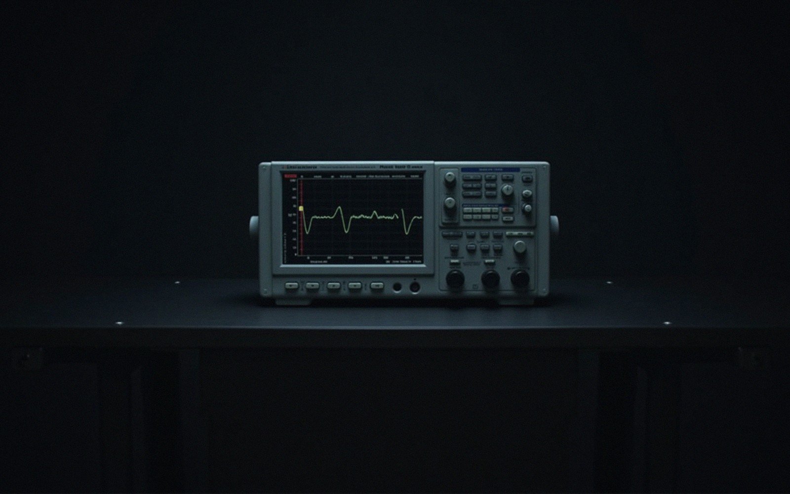
A multimeter cannot reliably measure microamp-range currents with millisecond transients. A precision shunt resistor with a fast ADC or a dedicated tool such as a Nordic PPK2 or similar power profiler is the practical approach. Place the shunt in series with the supply and capture over a full duty cycle including the wake transients. Average current in software estimates rarely match hardware reality, especially early in a design when peripheral clocks are still fully enabled.
Once you have a real current trace, the surprises are almost always in two places: peripherals left clocked that you forgot about, and wake-up transients that happen more often than the firmware logic suggests. Both are fixable, but only once you can see them.
The final budget is always a negotiation: wake less often, run faster when awake, sleep deeper between events, and switch off anything external that does not need to be on. No single mode or instruction does the work alone — it is the combination of a well-chosen sleep depth, a disciplined peripheral clock strategy, an honest external load analysis, and a regulator chosen for its quiescent current that makes a battery-powered design last months rather than days.