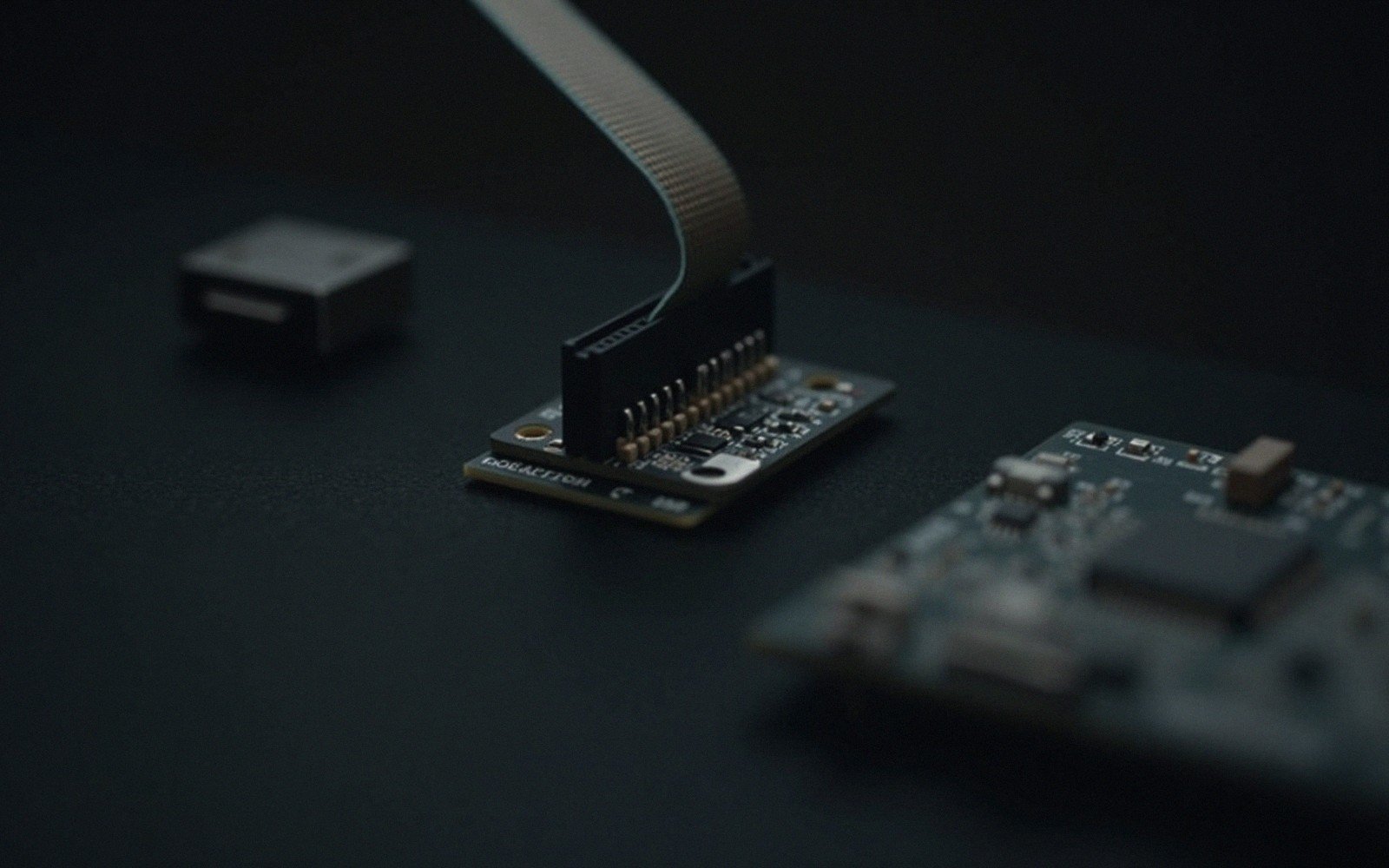
Programming socket, debug port, serial wire, or the chip's own boot code — each route has a job it does best.[1]
| Interface | Wires | What it does | Reach for it when |
|---|---|---|---|
| ISP | 3–4 + power | Programs the part in circuit through a peripheral it already has. | Production programming on a board with no debug need. |
| JTAG | 4–5 | Programs and debugs, and can chain several devices on one port. | Boards with several programmable parts, or boundary-scan test. |
| SWD | 2 + power | Programs and debugs over two wires — the usual choice on ARM parts. | Almost always, on anything Cortex-M, if you have the pins. |
| Bootloader | 2 (a serial port) or none | The part programs itself from code already resident in it. | Field updates, or where no programmer will ever be attached. |
§ 01The Problem Is Always the Same
You have compiled code and a blank chip. Somehow, bytes have to travel from your computer into the device's flash memory. The mechanism that bridges that gap is the programmer interface, and there are four distinct families of it you will encounter at the bench. They are not interchangeable in the way that USB cables are interchangeable. Each one reflects a different set of decisions about cost, access, speed and control — and choosing the right one early saves an afternoon of grief later.
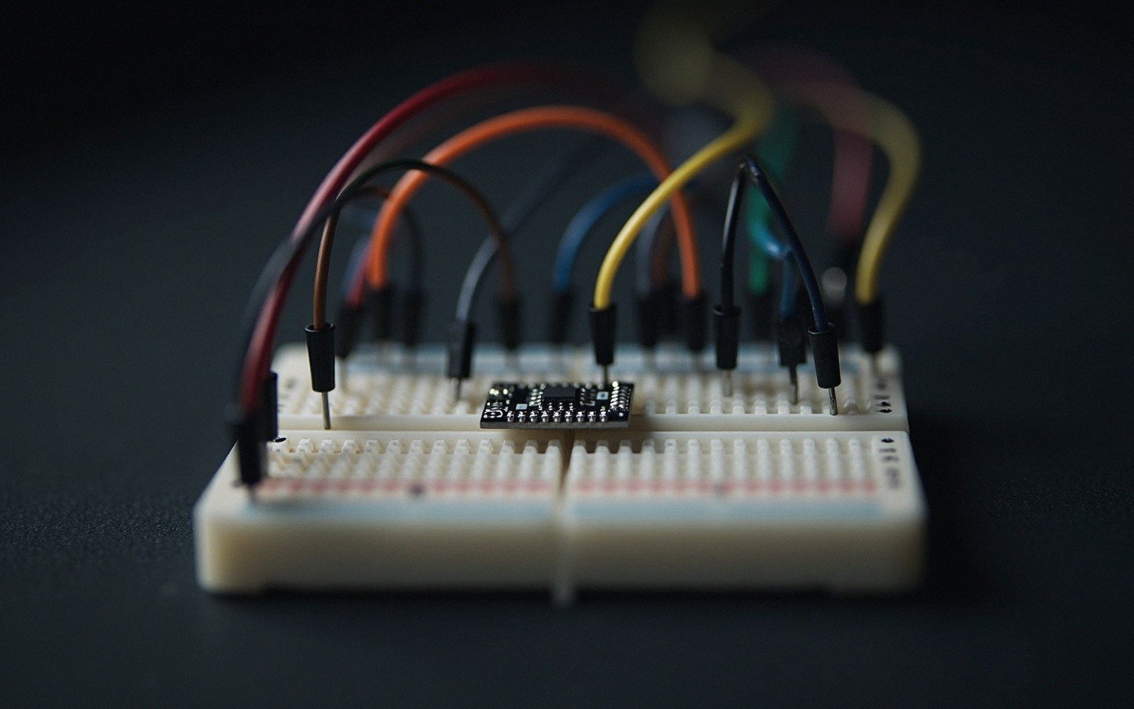 Enlarge ⤢
The four are: ISP (In-System Programming), JTAG (Joint Test Action Group), SWD (Serial Wire Debug), and the bootloader. They are not mutually exclusive — many chips support two or three simultaneously — but they differ sharply in what hardware they require, how much of the device they can reach, and whether they survive into production.[2]
§ 02ISP: Programming Without Pulling the Chip
ISP means the chip is programmed while it sits on the board, without socketing or removing it. In practice "ISP" usually describes a vendor-specific protocol — Microchip's ICSP (In-Circuit Serial Programming) for PIC and AVR families is the canonical example, and Atmel's (now Microchip's) AVR ISP is another. The chip exposes a small number of dedicated pins — commonly clock, data, and a programming-enable line — and a programmer tool bit-bangs or speaks SPI over them to write flash and EEPROM a page at a time.
The appeal is simplicity. You need a handful of pins, a modest programmer tool, and no dedicated debug infrastructure on the board. For AVR parts the six-pin ISP header became almost a convention; you can pick up a compatible programmer for very little, and the toolchain support is mature. Atmel Studio, AVRDUDE, and a dozen third-party tools all speak the protocol.
The limitation is that ISP, by itself, does not give you live debugging. You can write the program and read back flash to verify; you can set fuse bits that control clock source and brownout levels. But once the chip resets into user code, ISP steps aside. If the firmware crashes, ISP alone cannot tell you why. For production programming of a design that is already debugged, that is fine. For development, you often want more.
ISP also puts specific constraints on the PCB. The programming pins must not be driven by other circuitry while the programmer holds the bus. Pull-ups, LEDs and logic attached to MOSI/MISO/SCK can prevent a clean programming cycle or, worse, create conditions where the programmer appears to succeed but the data is corrupted. Designing the board with those conflicts in mind — and perhaps populating a small footprint header — is standard practice.
§ 03JTAG: The Boundary-Scan Standard That Became a Debug Port
JTAG was standardised by IEEE as 1149.1 in 1990, originally to test board-level interconnects. The idea was that chips could be chained together through a four-wire bus — TDI, TDO, TCK, TMS, plus an optional reset — and a test controller could shift data through the chain, probing pin states and verifying solder joints without a bed-of-nails fixture. The standard did not set out to be a programming or debug interface, but the on-chip scan infrastructure turned out to be enormously useful for both.
On a microcontroller or microprocessor, JTAG gives a debug probe direct access to the CPU's internal state: registers, the program counter, memory through an address bus, and — critically — the ability to halt execution, set breakpoints, and single-step. For complex 32-bit devices, RISC-V parts, and anything running a RTOS, this is the practical minimum for productive development. You need a debug adapter — J-Link, ST-LINK, CMSIS-DAP probes and many others speak JTAG — and four or five pins on the target.
JTAG's main cost is those pins. On a 100-pin device that is noise; on a 32-pin part those four or five pins represent a real fraction of the I/O budget. The protocol is also more complex to implement correctly on the PCB: signal integrity on TCK matters at higher speeds, and daisy-chaining multiple devices in a scan chain introduces opportunities for configuration errors. But for an MPU running Linux, or an FPGA being configured alongside a microcontroller, JTAG is usually the only option that gives full visibility.
§ 04SWD: ARM's Two-Wire Answer
When Arm designed the Cortex-M architecture, they built in a debug port but recognised that many Cortex-M targets would be small, pin-limited parts. JTAG's four active signals became two: SWDIO (bidirectional data) and SWCLK (clock). That is the Serial Wire Debug interface, and it is the dominant debug and programming route for essentially all Cortex-M devices — which covers an enormous share of the microcontrollers sold today, from the STM32 family to the RP2040 to Nordic's nRF5x series.
SWD and JTAG are not competing protocols so much as two physical layer options for the same underlying ARM Debug Interface (ADI) specification. Many Cortex-M chips expose both on the same pins, switchable by the debug probe. A CMSIS-DAP adapter — the open standard Arm defined for debug probes — speaks both, and software like OpenOCD or pyOCD handles the session on the host side. The result is that for most Cortex-M work, SWD is the default choice: fewer pins, same capability, essentially no downsides unless you need to chain multiple devices.
SWD delivers everything you want for embedded development: flash programming, halt-and-step debugging, register inspection, memory read and write, and RTOS-aware debugging through vendor extensions. A target-side UART-over-debug channel called SWO (Serial Wire Output) can carry printf-style trace without consuming a UART pin. For small Cortex-M boards it is worth routing SWDIO, SWCLK, and the optional SWO to a compact header even if you never intend to sell a debugging interface — the pads alone, unpopulated, are enough to clip a probe to during development.
§ 05The Bootloader: Firmware's Own Front Door
All three interfaces above require external hardware. A bootloader requires none. It is a small piece of code — either baked into the chip at the factory by the silicon vendor, or written by the developer and programmed first — that runs before the application and can accept new firmware over a standard interface the board already exposes: UART, USB, I2C, SPI, CAN, or whatever is wired up.
Many chips ship with a factory-installed ROM bootloader that is always present regardless of what is in user flash. STM32 parts have an extensive ROM bootloader that speaks UART, USB DFU, I2C, SPI and CAN, selectable through the BOOT0 pin state at reset. Microchip's PIC32 family carries a similar facility. These ROM bootloaders cannot be erased — they live in a separate memory region — and they provide a reliable fallback even on a board that has no debug header.
A developer-written bootloader sitting in the first pages of flash is more flexible: it can speak a custom protocol, verify a cryptographic signature on incoming images, enforce a rollback policy, or dual-bank between a running image and a candidate one. The trade-off is that it consumes flash and RAM, it must itself be reliable (a buggy bootloader can brick a device), and if it has a bug, updating it requires an out-of-band method — which usually means falling back to JTAG or SWD.
The bootloader's great advantage is field updates. Once a product is deployed, opening the case to attach a programmer is expensive. A bootloader with a network or wireless front end means firmware can be updated over the air — FOTA on cellular and Bluetooth devices, or simply an HTTP server on a Wi-Fi-connected part. For consumer and industrial products this is not a luxury, it is often a compliance requirement. The bootloader guide covers the engineering decisions in detail: flash layout, update validation, failure handling and the specific risks that come with any code that can rewrite itself.
§ 06Choosing at the Bench
The practical decision tree is straightforward. If the chip is a Cortex-M part, wire SWD to a header and use it for everything during development. If it is a legacy AVR or PIC without ARM internals, ISP is the natural route. If the target is a complex processor, FPGA or multi-device board, JTAG is the appropriate tool despite its pin cost. And at every stage of development, understand what bootloader the chip carries in ROM, because it is your insurance policy if something else goes wrong.
In production, the economics shift. A flying-probe ISP fixture or a bed-of-nails rig can program a hundred boards an hour without a debug adapter on every station. Many manufacturers use a JTAG or SWD programmer for the initial programming and test, then lock the debug port through read-out protection before the product ships — not because the bootloader is gone, but because the JTAG or SWD route, if left open, gives access to everything. Understanding these four paths means you know which door is open, which is locked, and which one is the one you built yourself.